
A4988 Stepper Motor Driver Carrier, Black Edition
A4988 Stepper Motor Driver Carrier, Black Edition
1 in stock
Couldn't load pickup availability
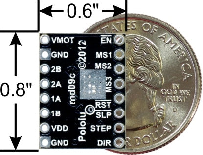
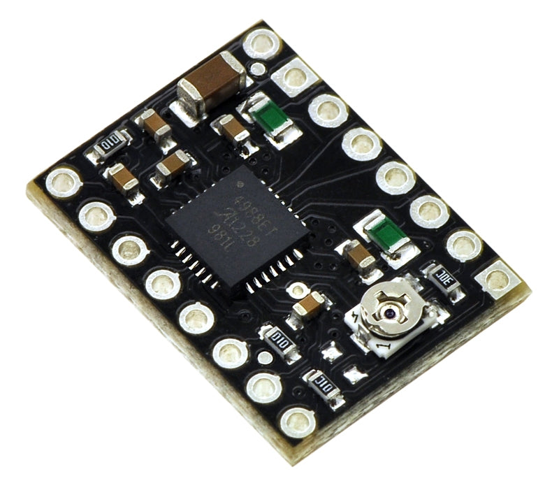
Like our original carrier, the Black Edition offers adjustable current limiting, over-current and over-temperature protection, and five different microstep resolutions. It operates from 8 V to 35 V and can deliver up to 2 A per coil with sufficient additional cooling. This board ships with 0.1″ male header pins included but not soldered in.
Overview
This product is a carrier board or breakout board for Allegro’s A4988 DMOS Microstepping Driver with Translator and Overcurrent Protection; we therefore recommend careful reading of the A4988 datasheet (1MB pdf) before using this product. This stepper motor driver lets you control one bipolar stepper motor at up to 2 A output current per coil (see the Power Dissipation Considerations section below for more information). Here are some of the driver’s key features:
Simple step and direction control interface
Five different step resolutions: full-step, half-step, quarter-step, eighth-step, and sixteenth-step
Adjustable current control lets you set the maximum current output with a potentiometer, which lets you use voltages above your stepper motor’s rated voltage to achieve higher step rates
Intelligent chopping control that automatically selects the correct current decay mode (fast decay or slow decay)
Over-temperature thermal shutdown, under-voltage lockout, and crossover-current protection
Short-to-ground and shorted-load protection
4-layer, 2 oz copper PCB for improved heat dissipation
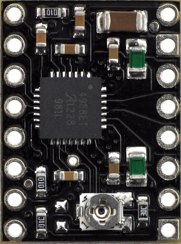
Exposed solderable ground pad below the driver IC on the bottom of the PCB
This product ships individually packaged with 0.1″ male header pins included but not soldered in; we also carry a version with male header pins already soldered in. For customers interested in higher volumes at lower unit costs, we offer a bulk-packaged version without header pins and a bulk-packaged version with header pins installed.
The Black Edition has the same component layout and pinout as our A4988 stepper motor driver carrier, so it can be used as a higher-performance drop-in replacement in applications designed for our original drivers. The Black Edition achieves its higher performance through its four-layer printed circuit board (PCB), which better draws heat out of the A4988 driver—while our original carrier can deliver up to approximately 1 A per phase in full-step mode without a heat sink or air flow, the Black Edition can deliver up to approximately 1.2 A under the same conditions.
For an even higher-performance alternative, please consider our DRV8825 stepper motor driver carrier, which can deliver more current over a wider voltage range. For lower-voltage applications, consider our DRV8834 carrier, which works with motor supply voltages as low as 2.5 V. Either of these boards can be used as a drop-in replacement for the Black Edition in many applications.
Some unipolar stepper motors (e.g. those with six or eight leads) can be controlled by this driver as bipolar stepper motors. For more information, please see the frequently asked questions. Unipolar motors with five leads cannot be used with this driver.
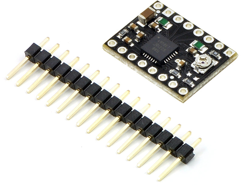
Included hardware
The A4988 stepper motor driver carrier comes with one 1×16-pin breakaway 0.1" male header. The headers can be soldered in for use with solderless breadboards or 0.1" female connectors. You can also solder your motor leads and other connections directly to the board. (A version of this board with headers already installed is also available.)
Using the driver
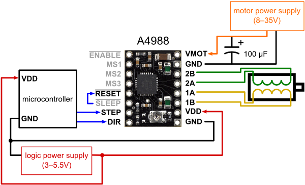
Minimal wiring diagram for connecting a microcontroller to an A4988 stepper motor driver carrier (full-step mode).
Power connections
The driver requires a logic supply voltage (3 – 5.5 V) to be connected across the VDD and GND pins and a motor supply voltage (8 – 35 V) to be connected across VMOT and GND. These supplies should have appropriate decoupling capacitors close to the board, and they should be capable of delivering the expected currents (peaks up to 4 A for the motor supply).
Warning: This carrier board uses low-ESR ceramic capacitors, which makes it susceptible to destructive LC voltage spikes, especially when using power leads longer than a few inches. Under the right conditions, these spikes can exceed the 35 V maximum voltage rating for the A4988 and permanently damage the board, even when the motor supply voltage is as low as 12 V. One way to protect the driver from such spikes is to put a large (at least 47 µF) electrolytic capacitor across motor power (VMOT) and ground somewhere close to the board.
Motor connections
Four, six, and eight-wire stepper motors can be driven by the A4988 if they are properly connected.
Warning: Connecting or disconnecting a stepper motor while the driver is powered can destroy the driver. (More generally, rewiring anything while it is powered is asking for trouble.)
Step (and microstep) size
Stepper motors typically have a step size specification (e.g. 1.8° or 200 steps per revolution), which applies to full steps. A microstepping driver such as the A4988 allows higher resolutions by allowing intermediate step locations, which are achieved by energizing the coils with intermediate current levels. For instance, driving a motor in quarter-step mode will give the 200-step-per-revolution motor 800 microsteps per revolution by using four different current levels.
The resolution (step size) selector inputs (MS1, MS2, and MS3) enable selection from the five step resolutions according to the table below. MS1 and MS3 have internal 100kΩ pull-down resistors and MS2 has an internal 50kΩ pull-down resistor, so leaving these three microstep selection pins disconnected results in full-step mode. For the microstep modes to function correctly, the current limit must be set low enough (see below) so that current limiting gets engaged. Otherwise, the intermediate current levels will not be correctly maintained, and the motor will skip microsteps.
| MS1 |
MS2 |
MS3 |
Microstep Resolution |
| Low |
Low |
Low |
Full Step |
| High |
Low |
Low |
Half Step |
| Low |
High |
Low |
Quarter Step |
| High |
High |
Low |
Eight Step |
| High |
High |
High |
Sixteenth Step |
Control inputs
Each pulse to the STEP input corresponds to one microstep of the stepper motor in the direction selected by the DIR pin. Note that the STEP and DIR pins are not pulled to any particular voltage internally, so you should not leave either of these pins floating in your application. If you just want rotation in a single direction, you can tie DIR directly to VCC or GND. The chip has three different inputs for controlling its many power states: RST, SLP, and EN. For details about these power states, see the datasheet. Please note that the RST pin is floating; if you are not using the pin, you can connect it to the adjacent SLP pin on the PCB to bring it high and enable the board.
Current limiting
To achieve high step rates, the motor supply is typically much higher than would be permissible without active current limiting. For instance, a typical stepper motor might have a maximum current rating of 1 A with a 5Ω coil resistance, which would indicate a maximum motor supply of 5 V. Using such a motor with 12 V would allow higher step rates, but the current must actively be limited to under 1 A to prevent damage to the motor.
The A4988 supports such active current limiting, and the trimmer potentiometer on the board can be used to set the current limit. One way to set the current limit is to put the driver into full-step mode and to measure the current running through a single motor coil without clocking the STEP input. The measured current will be 0.7 times the current limit (since both coils are always on and limited to 70% of the current limit setting in full-step mode). Please note that changing the logic voltage, Vdd, to a different value will change the current limit setting since the voltage on the “ref” pin is a function of Vdd.
Another way to set the current limit is to measure the voltage on the “ref” pin and to calculate the resulting current limit (the current sense resistors are 0.05Ω). The ref pin voltage is accessible on a via that is circled on the bottom silkscreen of the circuit board. The current limit relates to the reference voltage as follows:
Current Limit = VREF × 2.5
So, for example, if the reference voltage is 0.3 V, the current limit is 0.75 A. As mentioned above, in full step mode, the current through the coils is limited to 70% of the current limit, so to get a full-step coil current of 1.2 A, the current limit should be 1.2 A/0.7=1.7 A, which corresponds to a VREF of 1.7 A/2.5=0.68 V. See the A4988 datasheet for more information.
Note: The coil current can be very different from the power supply current, so you should not use the current measured at the power supply to set the current limit. The appropriate place to put your current meter is in series with one of your stepper motor coils.
Power dissipation considerations
The A4988 driver IC has a maximum current rating of 2 A per coil, but the actual current you can deliver depends on how well you can keep the IC cool. The carrier’s printed circuit board is designed to draw heat out of the IC, but to supply more than approximately 1.2 A per coil, a heat sink or other cooling method is required (in our tests, we were able to deliver approximately 1.4 A per coil with air flow from a PC fan and no heat sink).
This product can get hot enough to burn you long before the chip overheats. Take care when handling this product and other components connected to it.
Please note that measuring the current draw at the power supply will generally not provide an accurate measure of the coil current. Since the input voltage to the driver can be significantly higher than the coil voltage, the measured current on the power supply can be quite a bit lower than the coil current (the driver and coil basically act like a switching step-down power supply). Also, if the supply voltage is very high compared to what the motor needs to achieve the set current, the duty cycle will be very low, which also leads to significant differences between average and RMS currents.
Schematic diagram

Schematic diagram of the A4988 stepper motor driver carrier (both green and black editions).
Note: This board is a drop-in replacement for our original A4988 stepper motor driver carrier.