
QTR-3A Reflectance Sensor Array
QTR-3A Reflectance Sensor Array
14 in stock
Couldn't load pickup availability
Functional Description
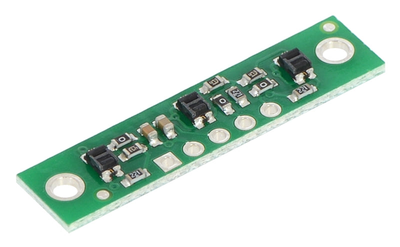
The QTR-3A reflectance sensor array is intended as a line sensor, but it can be used as a general-purpose proximity or reflectance sensor. The module is a convenient carrier for three IR emitter and receiver (phototransistor) pairs. With sensors spaced at intervals of 0.375″ (9.525 mm) along of the board’s longer axis, this array works well as a minimal detector for line-following robots, as line-following courses are commonly made using 3/4″ (19 mm) black electrical tape. The middle sensor is slightly offset along the short axis of the board.
Each phototransistor is connected to a pull-up resistor to form a voltage divider that produces an analog voltage output between 0 V and VCC (which is typically 5 V) as a function of the reflected IR. Lower output voltage is an indication of greater reflection.
The LED current-limiting resistors are set to deliver approximately 17 mA to the LEDs when VCC is 5 V, making the total board consumption just over 50 mA. The schematic diagram of the module is shown below:
This schematic is also available as a downloadable pdf (115k pdf).
For an alternative array with eight sensors and the ability to turn off the IR LEDs to limit power consumption, consider our QTR-8A reflectance sensor array. For individual reflectance sensors, consider our QTR-1A and QTR-L-1A.
QTR sensor size comparison. Clockwise from top left: QTR-3RC, QTR-1RC, QTR-L-1RC, QTR-8RC.
Specifications
Dimensions: 1.25″ × 0.3″ × 0.1″ (32 × 8 × 3 mm) (without header pins installed)
Operating voltage: 5.0 V
Supply current: 50 mA
Output format: 3 analog voltages
Output voltage range: 0 V to supplied voltage
Optimal sensing distance: 0.125" (3 mm)
Maximum recommended sensing distance: 0.25" (6 mm)
Weight without header pins: 0.02 oz (0.6 g)
There are several ways you can interface with the QTR-3A outputs:
Use a microcontroller’s analog-to-digital converter (ADC) to measure the voltages.
Use a comparator with an adjustable threshold to convert each analog voltage into a digital (i.e. black/white) signal that can be read by the digital I/O line of a microcontroller.
Connect each output directly to a digital I/O line of a microcontroller and rely upon its internal comparator.
QTR-1A output 1/8" away from a spinning white disk with a black line on it.
QTR-1A output 3/8" away from a spinning white disk with a black line on it.
Our Pololu AVR library provides functions that make it easy to use these sensors with our Orangutan robot controllers; please see the QTR Reflectance Sensors section of our library command reference for more information. We also have a Arduino library for these sensors.
Included Components
This module has two mounting holes intended for #2 screws (not included); if the mounting holes are not needed, the ends of the PCB can be ground off to make the unit even smaller (less than 1″ wide). The reflectance sensor array ships with a 1×5 straight male header strip and a1×5 right-angle male header strip as shown below. You can also solder wires, such as ribbon cable, directly to the pads for the smallest installation.